Modern LM340KC Variable Voltage Regulator Replacement
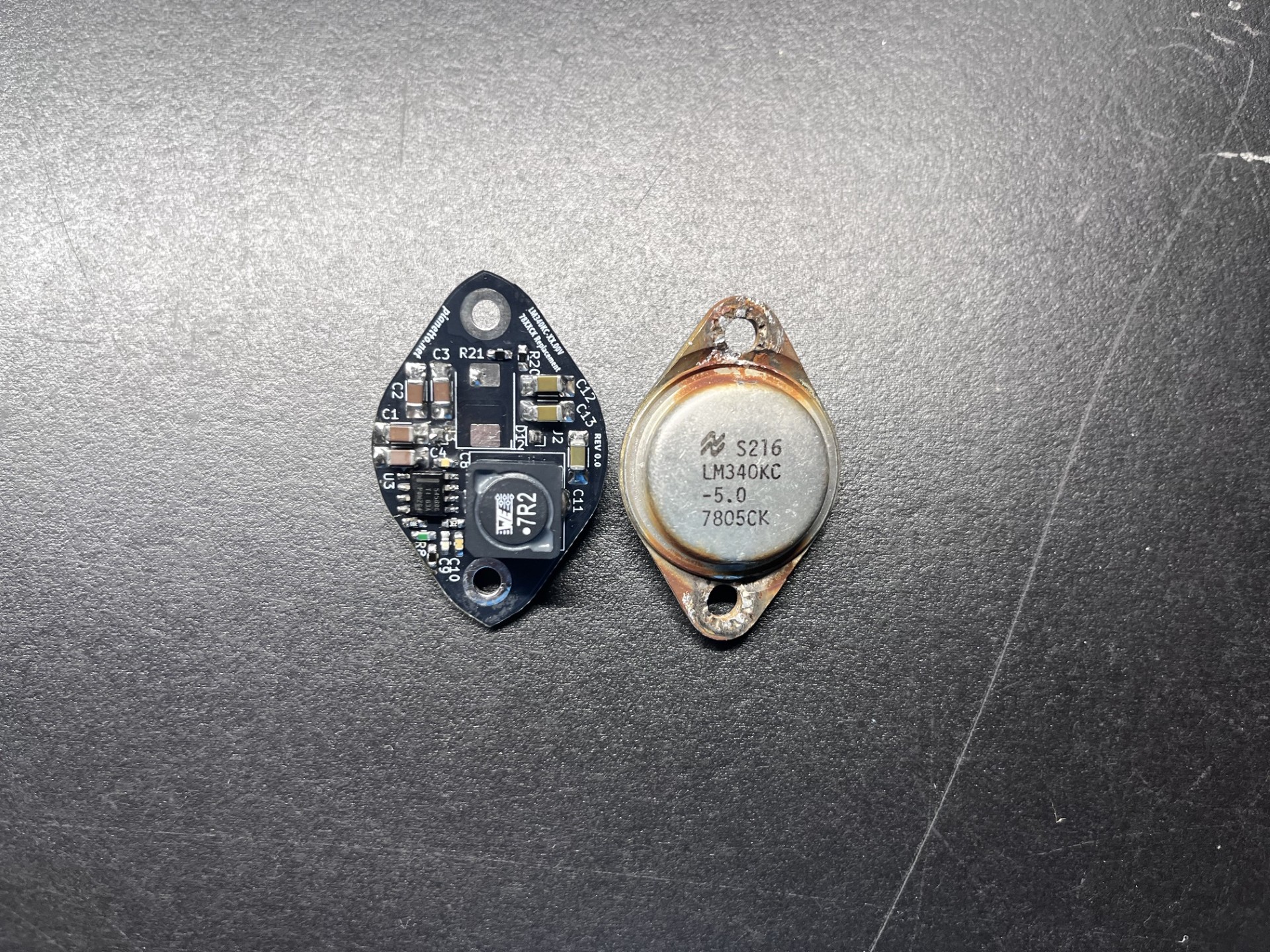
This was made using a DC-DC buck convertor that I had designed and used for my Senior Design project in college. I figured I could reuse my schematic and redid the board layout for use as a more efficient replacement for a vintage voltage regulator. Pictured here is what the PCB looked like before I had gotten a B560 diode, I have since then installed the diode and it works well in my MicroTerm Mime 2A from the 80's. I have it sitting next to a (broken) LM340.
This is designed with input filter capacitors rated for 25V, the MicroTerm 2A has a very crude diode rectifier power supply that turns the filtered 120VAC into 17VDC with slight ripple. This input line accepts this voltage just fine, and supplies the 12V and 5V in my vintage terminal using resistors to change the voltage output using feedback. I will get photographs when I am completed with this project.