Early Revision Macintosh 128K
Now that I have the entire Macintosh's casing and chasis cleaned, I think it is a good time to get started on the electrical repairs. Unlike the three Mime 2A terminals that I had previously worked on, the Macintosh 128k/512k models both have their schematics readily available online. Since both the logic board and the analog boards have been scanned and uploaded to the internet and I will be relying on them heavily.
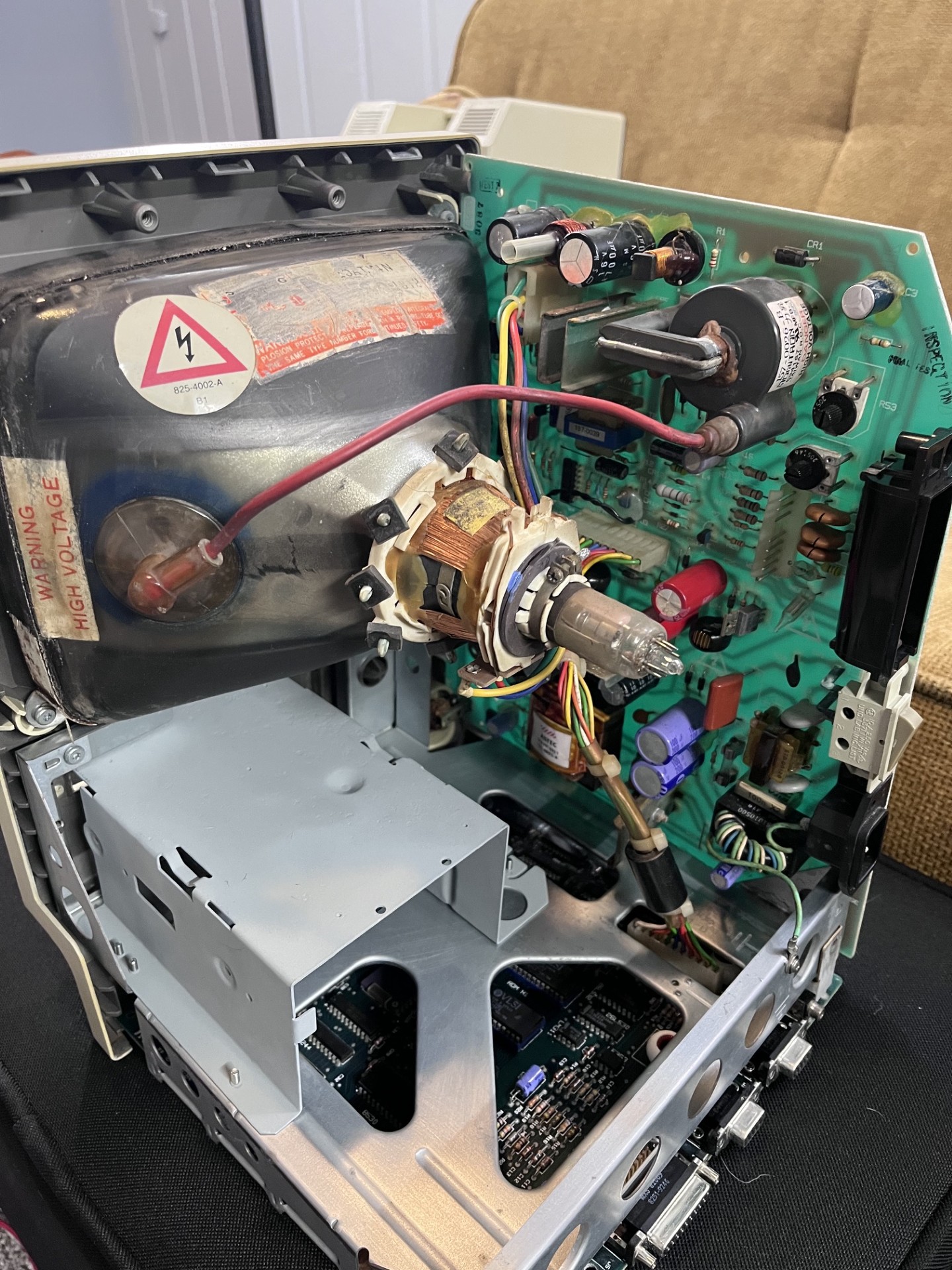
The board here on the right side in the vertical position is the "analog board", and is what it looked like after repairs. The more accurate name, as silkscreened on the PCB, is the "MACINTOSH SWEEP/POWER SUPPLY", but analog board rolls off the tongue a lot better so I will be refering to it as that.
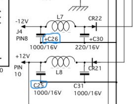
I initially noticed both C25 and C26 (the -12V and +12V filter capacitors) were bulging and replaced them with equivalent 1000uF 35V capacitors. Other than this, the rest of the board looked good to power on. The floppy drive port on the rear of the Macintosh has the +/-12V and +5V power rails, so testing these voltages is fairly easy. The power supply is a switch-mode power supply, but is of the older variety and requires a load. Because I do not own any 5-10ohm resistors at 10W ratings, I decided to plug in the motherboard so that the powersupply could operate correctly. Well, it did something...
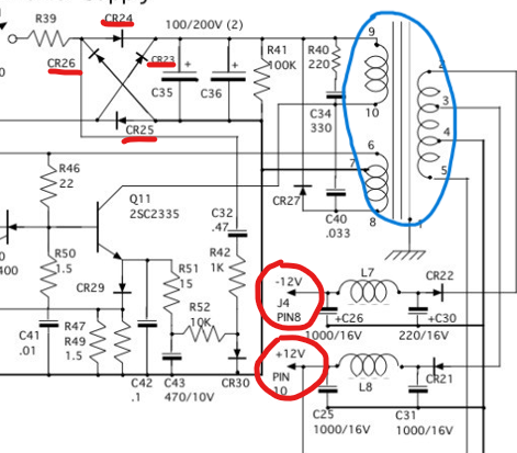
Turning on the Macintosh for the first time I got a low frequency hum with my +12V line delivering ~2.5V and the +5V line with only ~0.8V, obviously way underspecced. Eventually, the Macintosh would no longer power on and was completelty dead. After removing the machine from mains, I tested for shorts and found a direct short on the +5V, +/-12V to ground. The high voltage side ("sweep") that handles the flyback transformer for the 15kV CRT voltage is dependent on the low voltage power supply, so I will start my way from the bottom and I will not be labeling it suspect for now. My naive conclusion is that the windings in the ASTEC 157-0025-A (in blue) have shorted and are causing the voltage rails to fail. Another possible culprit could be diodes in the bridge rectifier. Checking these for shorts would be easy, and is a better starting point than purchasing a new transformer.
As I had finished some homework before nightfall arrived, and I figured that continuing to work on more labs and future homework would prove to be wasteful this deep into the night, I decided to continue on with the reapirs. I checked the entire motherboard for shorts, tested the bridge recitifer diodes in the primary windings section of the transformer in circuit, and finally reached a point where I needed to consult the Dead Mac Scrolls. The Dead Mac Scroll is a book published sometime in the 90's and covers the 128/512/Plus range of machines and details myriads of faults, common component failures, and general behavior of these machines. At this point, my Macintosh was dead as a door nail and I needed a bone thrown.
Reading on some of the common problems, there was a suggested component, R52, that could fail due to the proximity to an inductor that generated heat. Overtime this heat would damage the resistor, causing it to go out of spec. Well I decided to measure the resistor in circuit and it measured 40Mohms. Nope, something is wrong and at this point I susptected it had failed open. Desoldering it from the circuit showed that it was no longer a 10k resistor and instead was acting as a short.
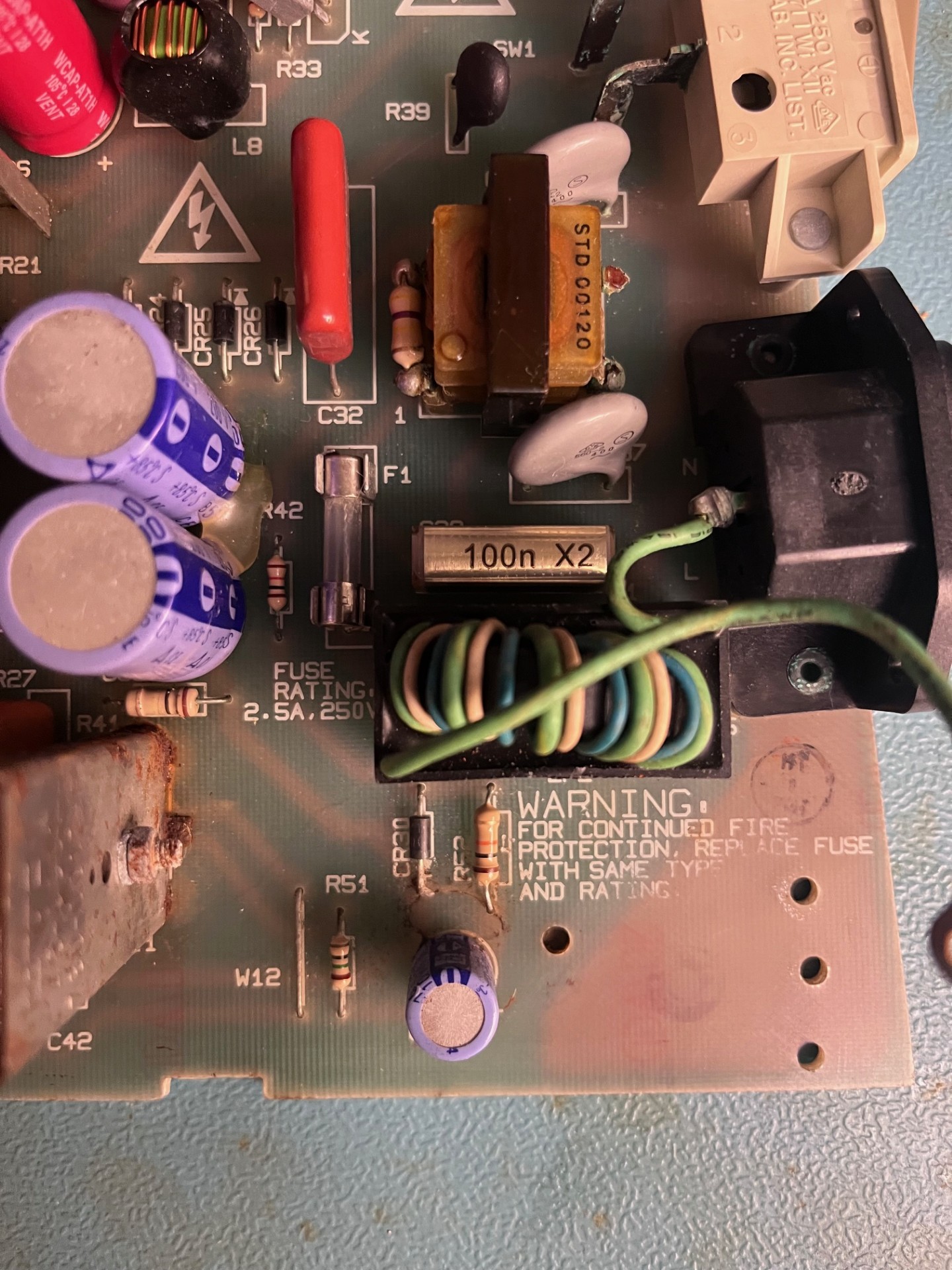
I replaced it with a 1/2W 10kOhm resistor, powered on the machine and...
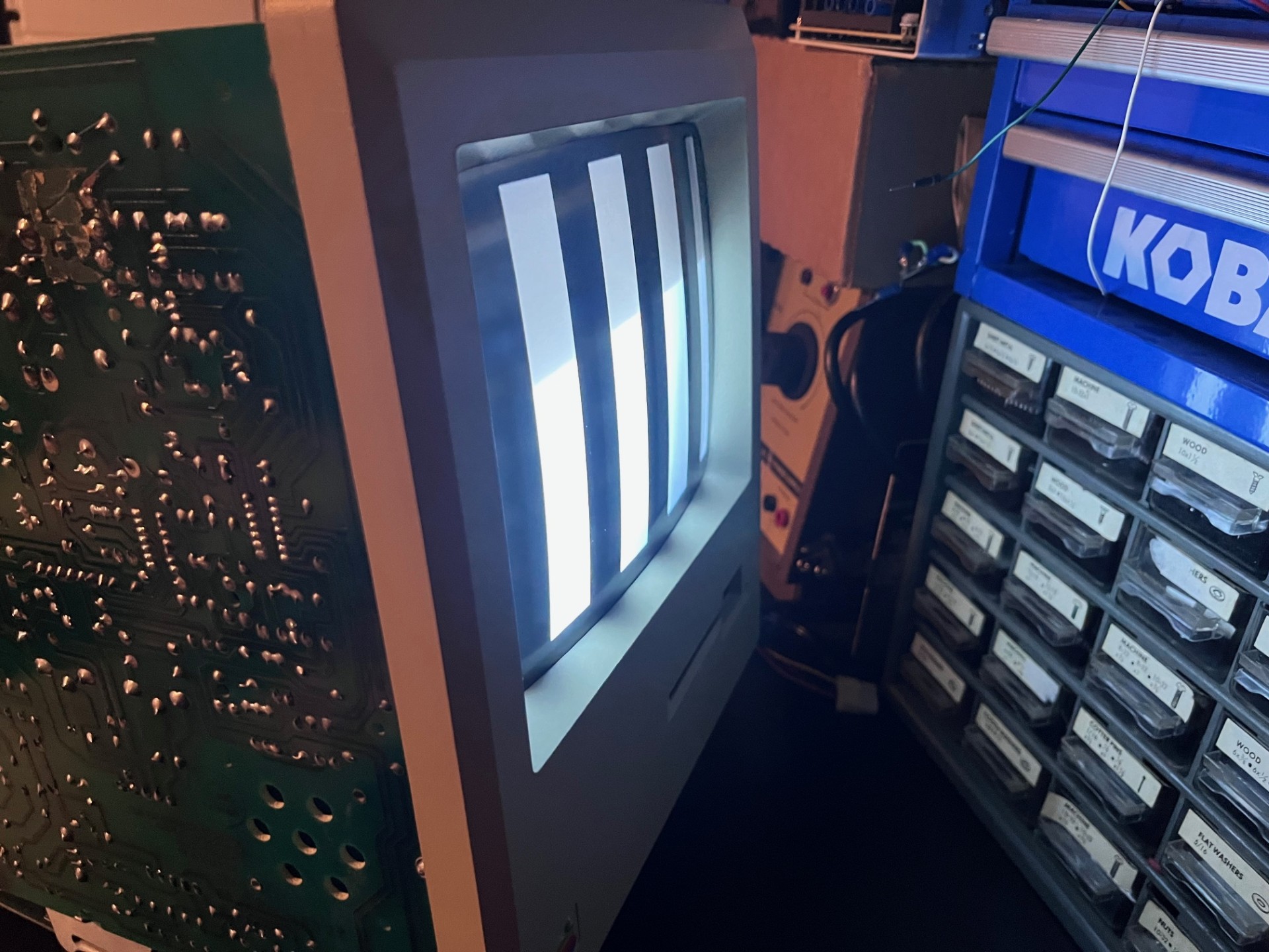
The Macintosh finally powers on for the first time in likely 32 years. This machine went from being stored in an abandoned office for most its life, open to the elements in the brutal Iowa weather, and to being able to power on (well, sort of). First of all, this screen is not good. We should be seeing a Happy Mac bootup screen + chime.
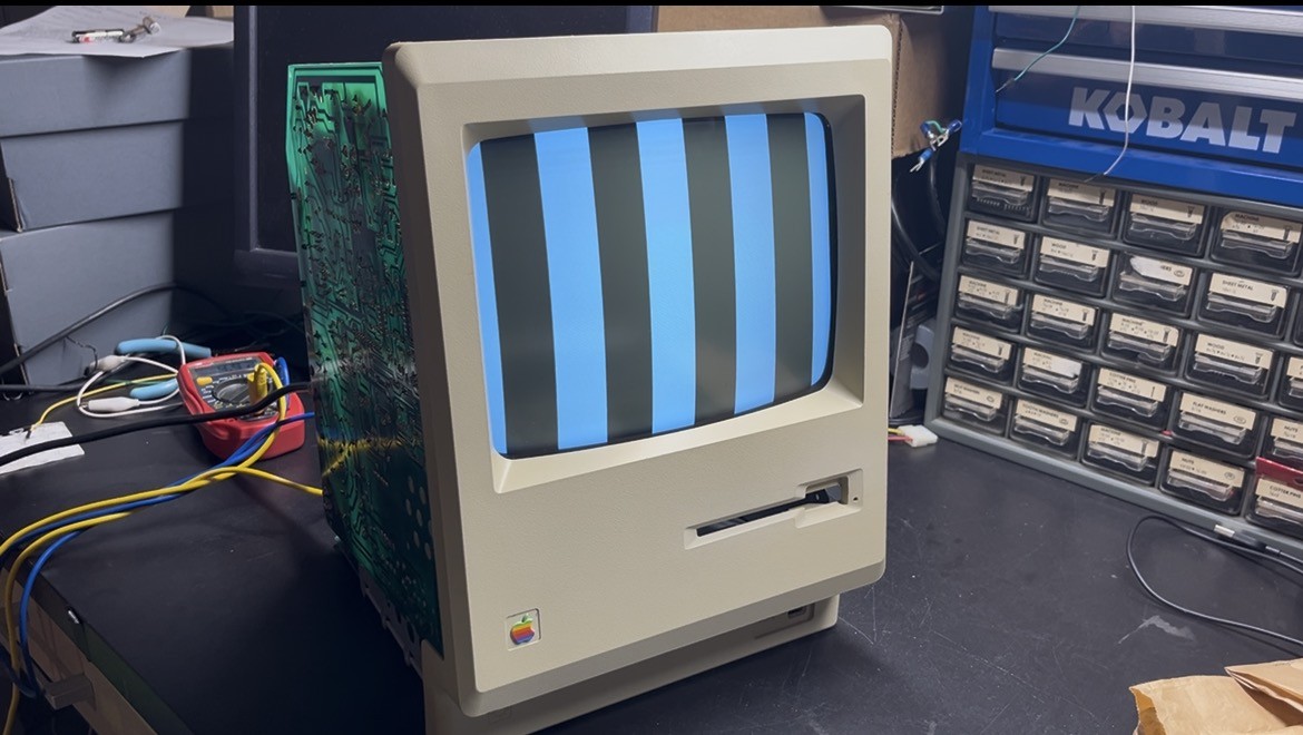
Second, this win did not last long. After a while of the machine being powered, I went to put the casing back on and the screen decided to no longer display anything. Brightness did nothing, it would simply briefly flash on startup, black screen, then flash when powered off. Bad connection with the wiring harness? I thought that might be the problem, but shaking, hitting, readjusting the PCB and harness did nothing. The heater filament in the neck was indeed glowing, and I was getting good 5V and +/-12V. Then I began hearing a loud high pitch squeeling, and at this point I decided to call it a night. I suspect the flyback may be failing, but I want to replace all the capacitors before I jump to that conclusion, but this will have to wait for now as I am very busy with school at the moment.
I came back to the Macinotsh after a little while, I just couldn't sleep without testing further, and was curious to see if perhaps I might have a bad solder joint somewhere on the board(s). With the entire system assmebled, I powered it on and it gave a high pitch squeal, I then proceeded to bang and hit the shell of the Macintosh and surprsingly the sound went away, and the screen picture came back on(?!).
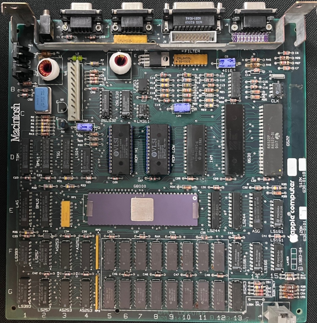
Further investigating, I decided to use some contact cleaner on the ROM HI/LOW sockets since the screen I saw on the initial power on test showed (likely) zero code being executed meaning perhaps a ROM was not seated or making good contact. Once I did that, I was able to get something that looked vaguely digital:
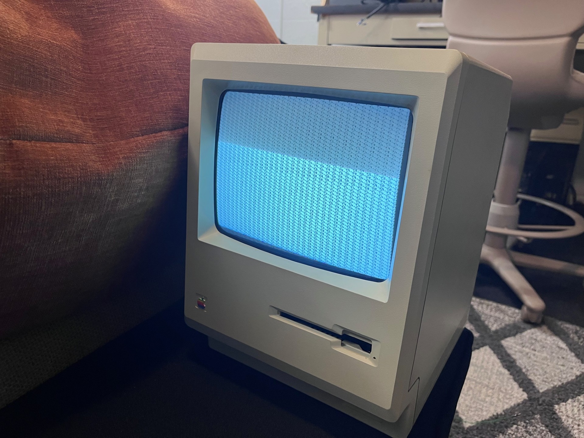
It does not resemble anything, but it looks like some pattern being replicated many times. I wonder if system memory decoding circuitry is bugged or if I have bad memory (but if I had bad memory, the ROMS would give me an error code showing where the bad memory was, right?!). While I hate doing a shotgun approach at replacing capacitors, I may have to do this on BOTH the logic board as well as the analog board since I am now noticing fluctuating analog board values, which is annoying since replacing capacitors at this scale is both time consuming, and is not a targeted repair.